SIMULATION BASICS / 7 MIN READ
DC, AC or transient? Choose the analysis that answers your question.
Three analyses, three questions. Real results from a divider, an RC filter and a rectifier show when to use a DC operating point, a transient run or an AC sweep.
By Simvolta · Updated
Start with the question, not the analysis.
Which analysis should you run? Pick the one that answers your question. A DC operating point tells you the steady state when nothing changes. A transient run tells you what happens over time, for any signal size and with nonlinear parts. An AC sweep tells you how a circuit responds to small sine waves across frequency.
The examples below use circuits from the Simvolta examples, and every number is a result from the desktop solver. Where a number is calculated rather than simulated, the guide says so.
DC operating point: the steady state.
A DC operating point solves the circuit with every source at its constant value, after everything has settled. Capacitors carry no current and inductors drop no voltage, so the result is a single set of node voltages and branch currents.
The voltage divider is the classic case: a 10 V source across two 1 kΩ resistors. The DC operating point reports 5 V at the midpoint and 5 mA through each resistor, which matches Ohm’s law exactly.
Use it to check bias points, power dissipation and polarity before anything else. It cannot show charging, oscillation or a waveform, because time is not part of the question.
V_out = V_in · R2 / (R1 + R2) = 10 V × 1 kΩ / 2 kΩ = 5 V
Transient: what happens over time.
A transient run steps through time and solves the full circuit at every step, including diodes, transistors and switches at any signal size. The result is a set of waveforms.
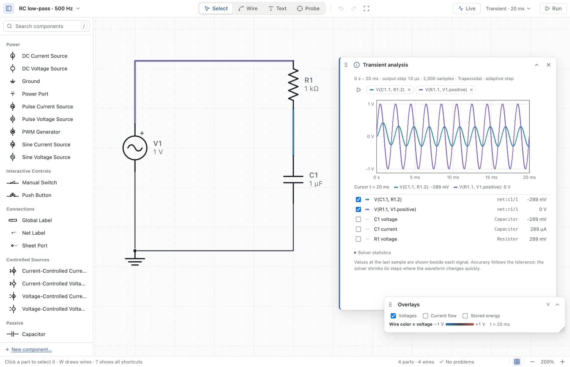
Drive the 1 kΩ, 1 µF RC low-pass filter with a 1 V peak, 500 Hz sine for 20 ms at a 10 µs output step, and the capacitor voltage settles to a 0.303 V peak that lags the input. Run a half-wave rectifier (10 V, 50 Hz, a diode and 1 kΩ) for 60 ms, and the load peaks at 9.29 V while the negative half cycles are blocked.
The rectifier shows why transient is sometimes the only valid choice: its behavior depends on the signal being large enough to switch the diode on and off. Two settings matter. The output step must resolve the fastest change you care about (10 µs gives 200 points per 500 Hz cycle). And the run must last long enough to settle, because it starts with no stored energy: compare settled cycles, not the first one.
AC sweep: the whole frequency question.
An AC sweep linearizes the circuit around its DC operating point and computes the gain and phase for a small sine at each frequency. The result is a Bode plot: one run instead of one transient per frequency.
Sweep the same RC filter from 1 Hz to 100 kHz at 50 points per decade with a 1 V AC magnitude, and the −3 dB corner appears at 159.1 Hz. The formula gives 159.15 Hz, so the measured corner sits within the sweep’s frequency spacing.
Because it is small-signal and linear, AC cannot show clipping, rectification or switching. Its amplitudes are relative, too: a 1 V AC magnitude simply makes the output read directly as gain.
f_c = 1 / (2π · R · C) = 1 / (2π × 1 kΩ × 1 µF) ≈ 159.15 Hz
Same circuit, two answers that agree.
For a linear circuit, AC and transient must agree once the transient has settled, and checking that is a good habit. At 500 Hz the RC filter’s f / f_c is exactly π (500 Hz × 2π × 1 kΩ × 1 µF), so the calculated gain is 0.3033. The settled transient peak measured in the desktop solver is 0.303303 V for a 1 V input: the same to four digits.
The calculated phase is −72.3°, a delay of about 0.40 ms at 500 Hz, which is the lag you can see between the input and output traces. When the two analyses disagree for a linear circuit, suspect the settings first: a transient that has not settled, or an output step too coarse to resolve the peak.
|H(500 Hz)| = 1 / √(1 + (f / f_c)²) = 1 / √(1 + π²) ≈ 0.3033
Common mistakes.
- Running an AC sweep with the source’s AC magnitude left at 0 V, its default in Simvolta. The response is then zero everywhere; set an AC magnitude, usually 1 V.
- Reading the first transient cycles as the steady state. A filter or rectifier starts from zero stored energy.
- Choosing an output step too coarse for the fastest edge or frequency, which flattens peaks and blurs edges.
- Using AC to judge a nonlinear effect such as clipping, rectification or switching. Run a transient instead.
- Expecting a DC operating point to show a capacitor charging. It only reports the final state.
A quick way to choose.
Ask what you want to know, then match it to the analysis. Live simulation is a continuous transient you can operate while it runs: switches, push buttons and PWM duty change the circuit without restarting the clock.
- What does the circuit settle to when nothing changes? Run a DC operating point.
- How does it respond over time, to a step, a pulse, a switch or a large signal? Run a transient.
- How do gain and phase change with frequency for small signals? Run an AC sweep.
- What happens when I flip this switch or change the duty cycle now? Go Live.